Garder les travailleurs en électricité hors danger : les outils sans contact – 1re partie
Premier de deux articles. La deuxième partie sera publiée le 25 novembre.
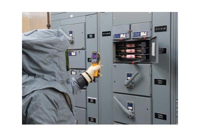
La base de tout programme de sécurité en électricité est simple : limiter l’exposition des travailleurs aux risques que représentent les chocs et les arcs électriques. Faire des tests implique souvent de travailler à l’intérieur des panneaux sous tension pour faire des diagnostics ou pour des entretiens de routine. Les travailleurs qui font ces tests sont exposés à des dangers réels. L’équipement de protection individuel représente un obstacle aux chocs et aux arcs, mais ne peuvent constituer la seule et principale source de protection pour les électriciens et les techniciens. Des pratiques de travail sécuritaires, comme l’utilisation d’outils de test sans contact ne met pas les travailleurs en danger. C’est peut-être la première chose à considérer quand on parle de sécurité électrique.
It’s the foundation of any electrical safety program: limiting the exposure of workers to the electrical hazards of shock and arc flash. Using test leads and clamps to probe inside a live panel when troubleshooting and performing routine maintenance always exposes workers to danger. Electrical personal protective equipment (PPE) is a last line of defence and must never be relied upon as the primary method of protecting electricians and technicians. Safe work practices, including the use of non-contact test tools that do not require electrical workers to place themselves in harm’s way, must first be considered when it comes to electrical safety.
Any time workers are exposed to electrical hazards they are required to establish boundaries and wear the appropriate arc-rated clothing and rubber insulating gloves. Non-contact measurements can offer major safety advantages:
• safely reducing the amount of PPE worn
• reducing the number of workers inside the boundary, and even
• completely moving the test technician or electrician outside of all boundaries and away from potential danger
It’s the foundation of any electrical safety program: limiting the exposure of workers to the electrical hazards of shock and arc flash. Using test leads and clamps to probe inside a live panel when troubleshooting and performing routine maintenance always exposes workers to danger. Electrical personal protective equipment (PPE) is a last line of defence and must never be relied upon as the primary method of protecting electricians and technicians. Safe work practices, including the use of non-contact test tools that do not require electrical workers to place themselves in harm’s way, must first be considered when it comes to electrical safety.
Any time workers are exposed to electrical hazards they are required to establish boundaries and wear the appropriate arc-rated clothing and rubber insulating gloves. Non-contact measurements can offer major safety advantages:
• safely reducing the amount of PPE worn
• reducing the number of workers inside the boundary, and even
• completely moving the test technician or electrician outside of all boundaries and away from potential danger
The simplest step
Among the simplest non-contact test tools to use are non-contact infrared (IR) thermometers. Using the tool’s pistol grip to point a laser beam where the temperature is to be measured produces a temperature reading on the display. The laser beam is only for “aiming” the tool at the area to be measured. The temperature detected depends upon the tool’s distance from the point of measurement. Care must be taken to achieve accurate results. See Figure 1.
When it comes to safety, using an IR thermometer means
• no climbing on ladders to check ventilation exhaust temperatures
• no reaching around hot temperature bands and barrels to troubleshoot process problems
• no reaching around rotating shafts to check for motor hot spots
• no reaching inside of live panels to check temperatures of components
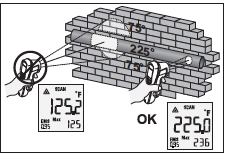
Figure 1. Using the IR thermometer allows technicians to stand at a safe distance from equipment and components to obtain accurate temperature data. Key to obtaining an accurate temperature is understanding that increasing the distance from the object measured decreases the accuracy of the reading since the thermometer takes an average of temperature of the area measured.
Visual infrared thermometers
A more advanced, yet practical tool is the visual IR thermometer. In addition to the standard IR thermometer features, the visual thermometer provides a digital image creating an infrared heat map — somewhat like a thermal imager. The visual IR thermometer is more accurate than the standard IR thermometer as it does not average in surrounding areas. Instead, the heat map is blended with a standard digital image so problem areas can be readily identified. See Figure 2.
You can download digital images to computer for further analysis and report generation, allowing you to work at safe distances well beyond shock and arc flash boundaries.
The heat map of the visual IR thermometer allows for quick identification of overheated conductors and terminations— potential fire hazards. Overheated contacts and electrical components could indicate pending equipment failures and possible arc flash issues. Identifying and reducing hazards is a goal of every safety program.
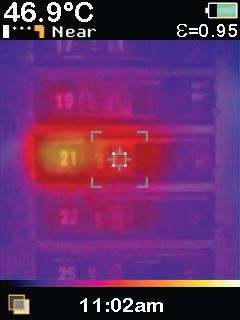
Figure 2. The Visual IR Thermometer blends the digital image of the object under measurement with the heat map indicating the now obvious to the unwary worker: This specific circuit breaker is overheating and poses a potential safety problem.
Using an infrared camera
Infrared cameras not only capture and measure the infrared (heat) energy emanating from a source, but produce a thermal image as well. Colours on the screen indicate the degree of heat coming from various components. Viewing a thermal image, especially when the standard digital image of the source is fused with the thermal image, produces a user-friendly picture for identifying potential problems. The operator can readily distinguish the difference in temperatures across the source image and quickly determine if corrective action is needed, and even how soon.
For example, when performing a thermal scan of electrical equipment, the InterNational Electrical Testing Association (NETA) notes that if a temperature difference between similar components under similar loading is between 4 °C and 15 °C, there is a problem with the higher temperature component and it should be repaired when possible. However, if that temperature difference between the similar components increases to greater than 15 °C, then immediate repairs should be completed.
Imagine one terminal on a three-phase breaker running significantly more than 15 °C hotter than the other two phases. Such an indication could mean a very high resistance at the terminal is producing dangerously high heat, insulation is beginning to soften and deform, and the breaker itself is near catastrophic failure. A non-contact measurement with a thermal imager identifies the potential failure in real time and, most importantly, keeps the technician at a much safer distance while diagnosing a potentially dangerous problem.
A person trained to use an infrared camera can function as part of a two-man team (the additional qualified person assists with setting up boundaries and opening enclosure doors) that can quickly move through a facility identifying overloaded circuits, faulty electrical and rotating mechanical equipment, and thermal process issues.
Averting potential safety problems by correcting before failure is another component of a safe work environment.
In the next issue of EIN: using
• an infrared (IR) window in conjunction with a thermal imager
• a laser distance meter
• non-contact voltage detectors
• remote display multimeters
• wireless tools
Source: Fluke Digital Library @ www.fluke.com/library.